Product Description
Industrial Couplings Transmission Parts Flange Rigid Pin Spacer HRC Mh Nm Fenaflex Spacer Motor Shaft Universal Half Oldham Tyre Drive Industrial Couplings
Application of Industrial Couplings
Industrial couplings are mechanical devices that are used to transmit torque and power from 1 shaft to another. They are used in a wide variety of industries, including:
- Material handling: Industrial couplings are used in material handling equipment, such as conveyor belts, elevators, and cranes.
- Power generation: Industrial couplings are used in power generation equipment, such as turbines and generators.
- Process industries: Industrial couplings are used in process industries, such as chemical plants and refineries.
- Machine tools: Industrial couplings are used in machine tools, such as lathes and milling machines.
- Transportation: Industrial couplings are used in transportation equipment, such as ships, trains, and airplanes.
There are many different types of industrial couplings, each with its own advantages and disadvantages. The type of coupling that is best suited for a particular application will depend on a number of factors, including the amount of torque that needs to be transmitted, the misalignment between the shafts, and the environmental conditions.
Some of the most common types of industrial couplings include:
- Jaw couplings: Jaw couplings are simple and rugged couplings that are easy to install and maintain. They are well suited for applications where there is a risk of misalignment.
- Gear couplings: Gear couplings are more expensive than jaw couplings, but they can transmit more torque and are less susceptible to misalignment.
- Hirth couplings: Hirth couplings are the most expensive type of industrial coupling, but they can transmit the most torque and are the least susceptible to misalignment.
Industrial couplings are an essential part of many industrial machines and systems. They play a vital role in the transmission of torque and power, and they help to ensure the safe and efficient operation of these machines and systems.
Here are some additional benefits of using industrial couplings:
- Increased efficiency: Industrial couplings can help to improve the efficiency of machines and systems by reducing friction and vibration.
- Reduced downtime: Industrial couplings can help to reduce downtime by preventing damage to machines and systems.
- Improved safety: Industrial couplings can help to improve safety by preventing machines and systems from becoming overloaded.
Overall, industrial couplings offer a number of benefits that can help to improve the efficiency, safety, and reliability of machines and systems.
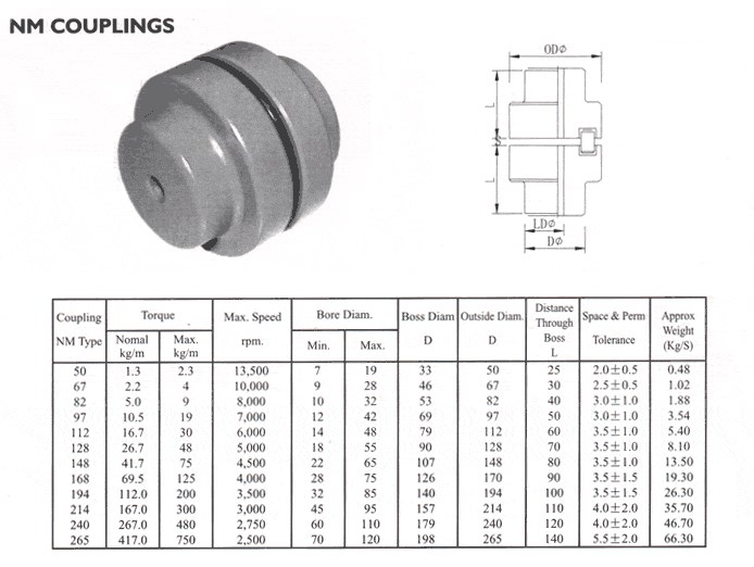
| Standard Or Nonstandard: | Standard |
|---|---|
| Shaft Hole: | 19-32 |
| Torque: | >80N.M |
| Bore Diameter: | 19mm |
| Speed: | 4000r/M |
| Structure: | Flexible |
| Samples: |
US$ 9999/Piece
1 Piece(Min.Order) | |
|---|
How does a flexible coupling handle angular, parallel, and axial misalignment?
A flexible coupling is designed to accommodate various types of misalignment between two rotating shafts: angular misalignment, parallel misalignment, and axial misalignment. The flexibility of the coupling allows it to maintain a connection between the shafts while compensating for these misalignment types. Here’s how a flexible coupling handles each type of misalignment:
- Angular Misalignment: Angular misalignment occurs when the axes of the two shafts are not collinear and form an angle with each other. Flexible couplings can handle angular misalignment by incorporating an element that can flex and bend. One common design is the “spider” or “jaw” element, which consists of elastomeric materials. As the shafts are misaligned, the elastomeric element can deform slightly, allowing the coupling to accommodate the angular offset between the shafts while still transmitting torque.
- Parallel Misalignment: Parallel misalignment, also known as offset misalignment, occurs when the axes of the two shafts are parallel but not perfectly aligned with each other. Flexible couplings can handle parallel misalignment through the same elastomeric element. The flexible nature of the element enables it to shift and adjust to the offset between the shafts, ensuring continuous power transmission while minimizing additional stresses on the machinery.
- Axial Misalignment: Axial misalignment, also called end-play misalignment, occurs when the two shafts move closer together or farther apart along their common axis. Flexible couplings can handle axial misalignment through specific designs that allow limited axial movement. For instance, some couplings use slotted holes or a floating member that permits axial displacement while maintaining the connection between the shafts.
By providing the capability to handle angular, parallel, and axial misalignment, flexible couplings offer several advantages for power transmission systems:
- They help to prevent premature wear and damage to the connected equipment, reducing maintenance and replacement costs.
- They minimize vibration and shock loads, enhancing the overall smoothness and reliability of the machinery.
- They reduce the risk of equipment failure due to misalignment-induced stresses, improving the system’s operational life.
- They allow for easier installation and alignment adjustments, saving time and effort during setup and maintenance.
Overall, flexible couplings play a crucial role in handling misalignment and ensuring efficient power transmission in various industrial applications.
What are the factors to consider when choosing a flexible coupling for a specific system?
Choosing the right flexible coupling for a specific system requires careful consideration of several factors. The following are the key factors that should be taken into account:
- 1. Misalignment Requirements: Assess the type and magnitude of misalignment expected in the system. Different couplings are designed to handle specific types of misalignment, such as angular, parallel, or axial misalignment. Choose a coupling that can accommodate the expected misalignment to prevent premature wear and failure.
- 2. Torque Capacity: Determine the required torque capacity of the coupling to ensure it can transmit the necessary power between the shafts. Consider both the continuous and peak torque loads that the system may experience.
- 3. Operating Speed: Take into account the rotational speed of the system. High-speed applications may require couplings that can handle the additional centrifugal forces and balance requirements.
- 4. Temperature Range: Consider the operating temperature range of the system. Select a coupling material that can withstand the temperatures encountered without losing its mechanical properties.
- 5. Environment and Conditions: Evaluate the environmental conditions where the coupling will be used, such as exposure to moisture, chemicals, dust, or corrosive substances. Choose a coupling material that is compatible with the operating environment.
- 6. Space Constraints: Assess the available space for the coupling installation. Some couplings have compact designs suitable for applications with limited space.
- 7. Installation and Maintenance: Consider the ease of installation and maintenance. Some couplings may require special tools or disassembly for maintenance, while others offer quick and simple installation.
- 8. Torsional Stiffness: Evaluate the torsional stiffness of the coupling. A balance between flexibility and stiffness is essential to prevent excessive torsional vibrations while accommodating misalignment.
- 9. Shock and Vibration Damping: For applications with high shock loads or vibration, select a coupling with excellent damping characteristics to protect the system from excessive forces.
- 10. Cost and Budget: Compare the cost of the coupling with the overall budget for the system. Consider the long-term cost implications, including maintenance and replacement expenses.
Ultimately, the choice of a flexible coupling should align with the specific requirements and operating conditions of the system. Consulting with coupling manufacturers or engineering experts can provide valuable insights to ensure the optimal selection of a coupling that enhances system performance, reliability, and efficiency.
What is a flexible coupling and how does it work?
A flexible coupling is a mechanical device used to connect two shafts while allowing for relative movement between them. It is designed to transmit torque from one shaft to another while compensating for misalignment, vibration, and shock. Flexible couplings are essential components in various rotating machinery and systems, as they help protect the connected equipment and enhance overall performance.
Types of Flexible Couplings:
There are several types of flexible couplings, each with its unique design and characteristics. Some common types include:
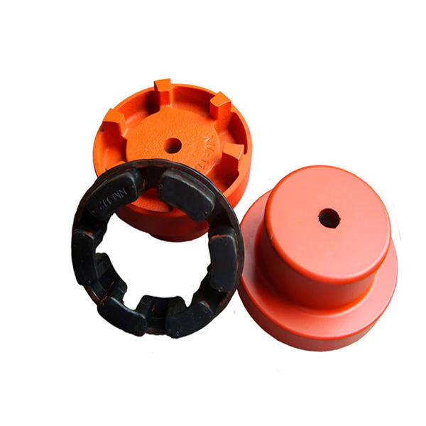
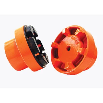
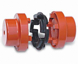
- Jaw Couplings: Jaw couplings feature elastomer spiders that fit between two hubs. They can accommodate angular and parallel misalignment while dampening vibrations.
- Disc Couplings: Disc couplings use thin metallic discs to connect the shafts. They are highly flexible and provide excellent misalignment compensation.
- Gear Couplings: Gear couplings use gear teeth to transmit torque. They offer high torque capacity and can handle moderate misalignment.
- Beam Couplings: Beam couplings use a single piece of flexible material, such as a metal beam, to transmit torque while compensating for misalignment.
- Bellows Couplings: Bellows couplings use a bellows-like structure to allow for axial, angular, and parallel misalignment compensation.
- Oldham Couplings: Oldham couplings use three discs, with the middle one having a perpendicular slot to allow for misalignment compensation.
How a Flexible Coupling Works:
The operation of a flexible coupling depends on its specific design, but the general principles are similar. Let’s take the example of a jaw coupling to explain how a flexible coupling works:
- Two shafts are connected to the coupling hubs on either side, with an elastomer spider placed between them.
- When torque is applied to one shaft, it causes the spider to compress and deform slightly, transmitting the torque to the other shaft.
- In case of misalignment between the shafts, the elastomer spider flexes and compensates for the misalignment, ensuring smooth torque transmission without imposing excessive loads on the shafts or connected equipment.
- The elastomer spider also acts as a damping element, absorbing vibrations and shocks during operation, which reduces wear on the equipment and enhances system stability.
Overall, the flexibility and ability to compensate for misalignment are the key features that allow a flexible coupling to function effectively. The choice of a specific flexible coupling type depends on the application’s requirements, such as torque capacity, misalignment compensation, and environmental conditions.


editor by CX 2023-10-05