Product Description
Fiber Optic Splitter Product Name
16 way pon fiber optic plitter fiber to fiber coupling
Fiber Optic Splitter Description:
PLC-Planar Lightwave Circuit Splitter is a kind of power splitter based on the integrated quartz baseplate.
Single Mode PLC 1×N and 2×N Splitter divide uniformly optical signals from 1 or 2 inputs to multiple
outputs, and spliter can be operated in reverse direction to combine multiple signals into fiber or 2 fibers.
Fiber Optic Splitter Features:
Low Insertion loss
Low PDL
Compact Design
Good channel-to-channel uniformity
Wide Operating Wavelength: From 1260nm to 1650nm
Wide Operating Temperature:From -40ºC to 85ºC
High Reliability and Stability
Fiber Optic Splitter Applications
FTTX Systems
PON Networks
CATV Links
Optical Signal Distribution
Fiber Optic Splitter Compliance
Telcordia GR-1209-CORE
Telcordia GR-1221-CORE
RoHS
Fiber Optic Splitter Specifications
Table 1 – 1×N PLC Splitter
| Parameters | 1×2 | 1×4 | 1×8 | 1×16 | 1×32 | 1×64 |
| Operating Wavelength (nm) | 1260~1650 | |||||
| Fiber Type | G657A or customer specified | |||||
| Insertion Loss (dB)(P/S Grade) | 3.8/4.0 | 7.1/7.3 | 10.2/10.5 | 13.5/13.7 | 16.5/16.9 | 20.5/21.0 |
| Loss Uniformity (dB) | 0.4 | 0.6 | 0.8 | 1.2 | 1.5 | 2.0 |
| Return Loss (dB) | 55 | 55 | 55 | 55 | 55 | 55 |
| Polarization Dependent Loss(dB) | 0.2 | 0.2 | 0.2 | 0.25 | 0.3 | 0.35 |
| Directivity (dB) | 55 | 55 | 55 | 55 | 55 | 55 |
| Wavelength Dependent Loss(dB) | 0.3 | 0.3 | 0.3 | 0.5 | 0.5 | 0.5 |
| Temperature Stability(-40~85 | 0.4 | 0.4 | 0.4 | 0.5 | 0.5 | 0.5 |
| ºC)(dB) | ||||||
| Operating Temperature (ºC) | -40~85 | |||||
| Storage Temperature (ºC) | -40~85 | |||||
| Device Dimension (mm) | 40×4×4 | 40×4×4 | 40×4×4 | 50×4×4 | 50×7×4 | 60×12×4 |
| (L×W×H) | ||||||
| Module Dimension (mm) | 100×80×10 | 100×80×10 | 100×80×10 | 120×80×18 | 140×115×18 | 140×115×18 |
| (L×W×H) | ||||||
| Mini-Module Dimension (mm) | 50×7×4 | 50×7×4 | 60×7×4 | 60×12×4 | 80×20×6 | N/A |
| (L×W×H) | ||||||
| Table 2 – 2×N PLC Splitter | ||||||
| Parameters | 2×2 | 2×4 | 2×8 | 2×16 | 2×32 | 2×64 |
| Operating Wavelength (nm) | 1260~1650 | |||||
| Fiber Type | G657A or customer specified | |||||
| Insertion Loss (dB) | 4.0 | 7.6 | 11.0 | 14.4 | 17.5 | 21.0 |
| Loss Uniformity (dB) | 0.6 | 1.0 | 1.2 | 1.5 | 1.8 | 2.2 |
| Return Loss (dB) | 55 | 55 | 55 | 55 | 55 | 55 |
| Polarization Dependent Loss(dB) | 0.2 | 0.2 | 0.3 | 0.3 | 0.4 | 0.4 |
| Directivity (dB) | 55 | 55 | 55 | 55 | 55 | 55 |
Notes:
Specified without connectors.
Add an additional 0.15dB loss per connector.
FQA :
1. Q: Are you a manufacturer?
A: yes, we are a manufacturer , FTTH solution and data center total solution provider in HangZhou, China, established in 2000.
2. Q: What’s your MOQ?
A: MOQ can be 1 pcs, but the price is not competitive.More quantity,the price will be more competitive.
3. Q: Can you quote FOB price?
A: yes. We can delivery by air, DHL, TNT, UPC, FEDEX, etc. For big quantity we will deliver it by sea.
We can quote price with freight and lead time for you, after you let us know detailed requirements with quantity.
We have competitive shipping forwarders. For more solutions, you can feel free to contact us.
4. Q: How is your quality?
A: Our production is according to IEC, Europe standard. CE, ISO, RoHS, CPR, and ANATEL certified.
All the products are 100% test before delivery.
5. Q: What’s your lead time?
A: It depends on the quantity and products. For fiber optic patch cord, the lead time can be 2 -3 working days within 5000 pcs. We keep the regular products in stock. Also, we can deal with urgent orders.
6. Q: What’s your warranty?
A: Depends 1 different product, we have1 years warranty for patch cord since delivery, but only responsible for non-artificial damage. For artificial damage, we can repair it for you for free, freight will be paid by your side.
7. Q: What’s your packing?
A: International export standard package.If you need to print your logo on the packing, please let us know before we quote.
8. Q: Can you offer OEM/ODM?
A: yes, we can. all products accept OEM /ODM. we can CHINAMFG the Confidentiality Agreement.
9. Q: Can I have a sample?
A: It depends on which products, Free sample provide under 10 usd. Freight will be paid by buyer before delivery.
10. Q: How can I order?
A:1.send mail or inquiries with product name, specification, and quantity to us . Provide your receive address if you need FOB,CIF,CFR price.
2.We will offer our quotation with lead time.
3.After the quotation confirmed, we will send a PI with our bank account.
4.Production will be arranged after the payment received.
5.Confirm the consignee with you before we deliver it.
6.The tracking number will be provided after the delivery.
11. Q: What your payment term?
A: T/T, Western Union, Paypal, MoneyGram at once. For big amounts, can be 50% deposit in advance, 50% balance paid before delivery.
Workshop:
Certificates:
ISO9001, ISO1400, CE, RoHS, CPR, ANATEL certified
Exhibitions:
OFC, CommunicAsia, ECOC, Netcom, SVIAZ ICT, AFRICACOM, CAIRO ICT, etc.
|
Shipping Cost:
Estimated freight per unit. |
To be negotiated |
|---|
| Type: | Fiber Optic Splitter&Coupler |
|---|---|
| Wiring Devices: | ODF |
| Certification: | CE, ISO, RoHS, GS |
| Samples: |
US$ 10/Piece
1 Piece(Min.Order) | Order Sample |
|---|
| Customization: |
Available
| Customized Request |
|---|
How does a flexible coupling handle angular, parallel, and axial misalignment?
A flexible coupling is designed to accommodate various types of misalignment between two rotating shafts: angular misalignment, parallel misalignment, and axial misalignment. The flexibility of the coupling allows it to maintain a connection between the shafts while compensating for these misalignment types. Here’s how a flexible coupling handles each type of misalignment:
- Angular Misalignment: Angular misalignment occurs when the axes of the two shafts are not collinear and form an angle with each other. Flexible couplings can handle angular misalignment by incorporating an element that can flex and bend. One common design is the “spider” or “jaw” element, which consists of elastomeric materials. As the shafts are misaligned, the elastomeric element can deform slightly, allowing the coupling to accommodate the angular offset between the shafts while still transmitting torque.
- Parallel Misalignment: Parallel misalignment, also known as offset misalignment, occurs when the axes of the two shafts are parallel but not perfectly aligned with each other. Flexible couplings can handle parallel misalignment through the same elastomeric element. The flexible nature of the element enables it to shift and adjust to the offset between the shafts, ensuring continuous power transmission while minimizing additional stresses on the machinery.
- Axial Misalignment: Axial misalignment, also called end-play misalignment, occurs when the two shafts move closer together or farther apart along their common axis. Flexible couplings can handle axial misalignment through specific designs that allow limited axial movement. For instance, some couplings use slotted holes or a floating member that permits axial displacement while maintaining the connection between the shafts.
By providing the capability to handle angular, parallel, and axial misalignment, flexible couplings offer several advantages for power transmission systems:
- They help to prevent premature wear and damage to the connected equipment, reducing maintenance and replacement costs.
- They minimize vibration and shock loads, enhancing the overall smoothness and reliability of the machinery.
- They reduce the risk of equipment failure due to misalignment-induced stresses, improving the system’s operational life.
- They allow for easier installation and alignment adjustments, saving time and effort during setup and maintenance.
Overall, flexible couplings play a crucial role in handling misalignment and ensuring efficient power transmission in various industrial applications.
What role does a flexible coupling play in reducing downtime and maintenance costs?
A flexible coupling plays a significant role in reducing downtime and maintenance costs in industrial machinery and rotating equipment. Here are the key ways in which flexible couplings contribute to these benefits:
- Misalignment Compensation: One of the primary functions of a flexible coupling is to accommodate misalignment between two connected shafts. Misalignment can occur due to various factors such as thermal expansion, foundation settling, or manufacturing tolerances. By allowing for misalignment, flexible couplings reduce the transmission of harmful forces and stresses to connected components, minimizing wear and preventing premature failures that could lead to costly downtime and repairs.
- Vibration Damping: Flexible couplings have inherent damping properties due to the elastomeric or flexible elements they incorporate. These elements absorb and dissipate vibration and shock loads that may arise from the operation of rotating machinery. By dampening vibrations, flexible couplings protect the connected equipment from excessive wear and fatigue, extending their service life and reducing the need for frequent maintenance or replacement.
- Shock Load Absorption: In applications where sudden loads or shocks are common, such as in heavy machinery or high-speed equipment, flexible couplings act as shock absorbers. They can absorb and dissipate the impact energy, preventing damage to the machinery and minimizing downtime caused by unexpected failures or breakdowns.
- Easy Installation and Alignment: Flexible couplings are designed for ease of installation and alignment. Unlike rigid couplings that require precise shaft alignment, flexible couplings can tolerate some degree of misalignment during installation. This feature simplifies the setup process, reduces installation time, and lowers the risk of misalignment-related issues, ultimately minimizing downtime during initial installation or replacement of couplings.
- Reduced Maintenance Frequency: The ability of flexible couplings to handle misalignment and dampen vibrations results in reduced wear on bearings, seals, and other connected components. Consequently, the frequency of maintenance intervals can be extended, reducing the need for frequent inspections and component replacements. This directly translates to lower maintenance costs and less downtime for maintenance tasks.
- Equipment Protection: By reducing the transmission of shock loads and vibrations, flexible couplings act as protective barriers for connected equipment. They help prevent catastrophic failures and subsequent damage to expensive machinery, avoiding unplanned shutdowns and costly repairs.
Overall, flexible couplings are critical components that improve the reliability and longevity of rotating equipment. Their ability to handle misalignment, dampen vibrations, and protect against shock loads contributes to reduced downtime, lower maintenance costs, and increased productivity in industrial applications.
Can you explain the different types of flexible coupling designs available?
There are several types of flexible coupling designs available, each with its unique construction and characteristics. These designs are tailored to meet specific application requirements and address different types of misalignment and torque transmission needs. Here are some of the most common types of flexible couplings:
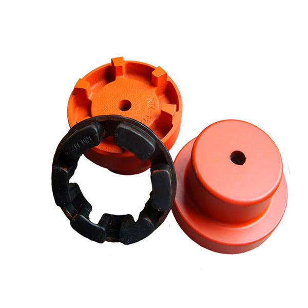
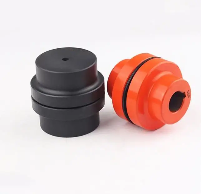
- Jaw Couplings: Jaw couplings consist of two hubs with curved jaws and an elastomer spider placed between them. The spider acts as a flexible element and can compensate for angular and parallel misalignment. Jaw couplings are widely used in various industrial applications due to their simple design and effectiveness in handling misalignment and vibration damping.
- Disc Couplings: Disc couplings use thin metallic discs with a series of alternating slits and flanges to connect the shafts. The disc coupling design allows for excellent misalignment compensation, including angular, parallel, and axial misalignment. Disc couplings are known for their high torsional stiffness and precise torque transmission capabilities.
- Gear Couplings: Gear couplings consist of toothed hubs connected by an external sleeve with gear teeth. They are well-suited for applications with high torque and moderate misalignment. Gear couplings offer good misalignment compensation and high torque capacity, making them popular in heavy-duty industrial applications.
- Beam Couplings: Beam couplings use a single piece of flexible material, often a metal beam, to connect the shafts. The material’s flexibility allows for angular and axial misalignment compensation. Beam couplings are compact, lightweight, and provide low inertia, making them suitable for applications with high-speed requirements.
- Bellows Couplings: Bellows couplings consist of a bellows-like flexible structure that connects the two hubs. They can compensate for angular, parallel, and axial misalignment. Bellows couplings are known for their high torsional stiffness and ability to maintain constant velocity transmission.
- Oldham Couplings: Oldham couplings use three discs, with the middle one having a perpendicular slot. This design allows for angular misalignment compensation while transmitting torque between the hubs. Oldham couplings are often used when electrical isolation between shafts is required.
Each flexible coupling design has its strengths and limitations, and the choice depends on factors such as the application’s torque requirements, misalignment conditions, operating environment, and speed. Proper selection of the coupling type ensures optimal performance, efficiency, and reliability in various mechanical systems and rotating machinery.


editor by CX 2023-09-29