Kopling Rahang Fleksibel NM 82
NM 82 reference model with 10-32 mm bore range, 8000 rpm maximum reference speed, and forged-iron hub construction shown in the supplied reference page. Final bore, keyway and duty require confirmation.
NM 82 sits between the compact and mid-size entries in the supplied table. Reference values are 5.0 Kg*m normal torque, 9 Kg*m maximum torque, 8,000 rpm maximum speed, 10-32 mm bore range, 82 mm outside diameter and about 1.88 kg. That combination makes it a logical model to review when the shaft has moved beyond NM 67 but the drive still needs a relatively small package.
- Reference normal torque 5.0 Kg*m
- Bore range starts at 10 mm
- Outside envelope 82 mm
- Check duty independently from shaft size
- Use an approved fit/key drawing
Intermediate Size Snapshot
For NM 82, the supplied figures are reproduced without changing units. Treat them as a shortlist tool, then close the shaft, duty and environment questions before purchase release.
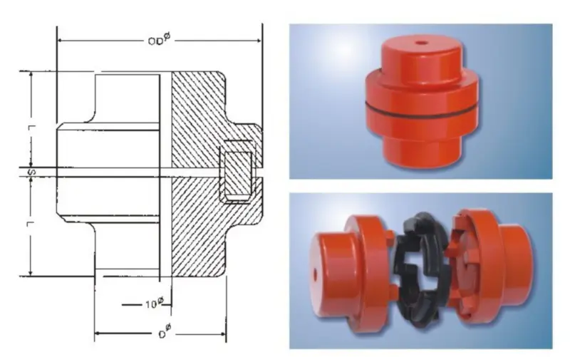
| Model | Normal Torque (Kg*m) | Max Torque (Kg*m) | Max RPM | Bore Min (mm) | Bore Max (mm) | Boss D (mm) | Outside OD (mm) | Distance L (mm) | Space S (mm) | Approx. Weight (kg) |
|---|---|---|---|---|---|---|---|---|---|---|
| NM 82 | 5.0 | 9 | 8000 | 10 | 32 | 53 | 82 | 40 | 3.0±1.0 | 1.88 |
Mechanical Layout
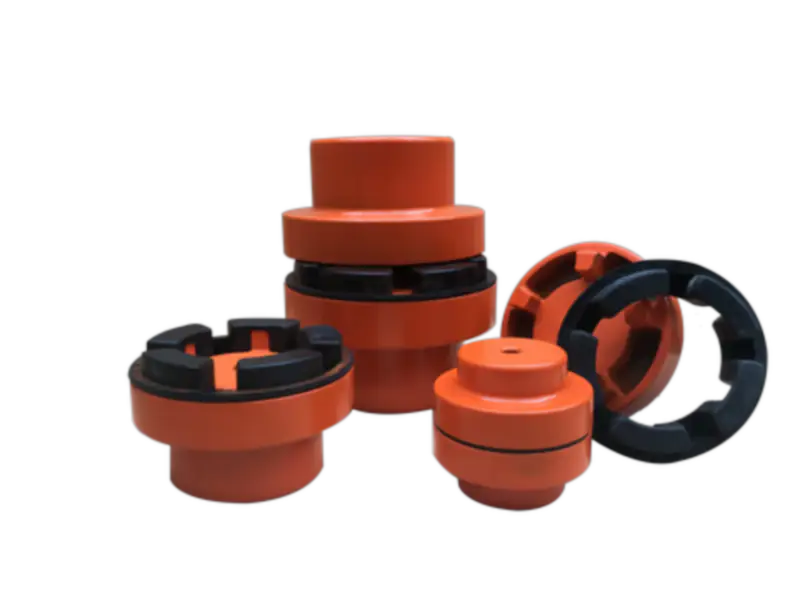
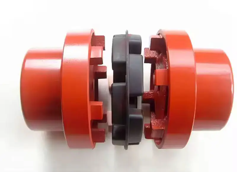
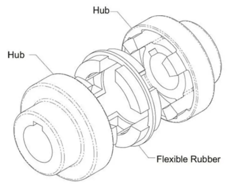
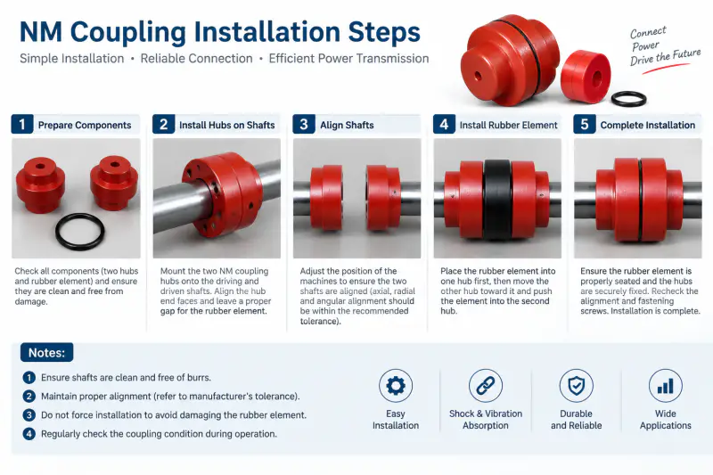
The supplied NM 82 imagery shows the familiar jaw-coupling architecture: two machined hubs and a central flexible member. Hub material is identified as forged iron on the reference page. The flexible member is not assigned a compound in the technical table, so procurement documents should specify service temperature and media exposure if those factors matter. This avoids treating a visual match as a full material specification.
Three-Limit Check
For NM 82, compare three limits together: torque, speed and bore. Begin with the larger shaft and keyway, then verify the machine torque including start-up behavior. The maximum speed in the table is a reference ceiling for model matching, not permission to operate at that value without reviewing balance, bore, fit and application conditions. If the driver has a high starting ratio or the driven inertia is large, state it explicitly.
Commissioning Focus
Before fitting NM 82, check shaft runout and remove burrs from keys and bore edges. Position the hubs to the drawing rather than estimating the center gap from the flexible element. Misalignment should be corrected at the machines, not consumed intentionally as a normal installation allowance. After the first operating period, inspect the element faces and hub positions for movement, debris or asymmetric wear.
Duty Context
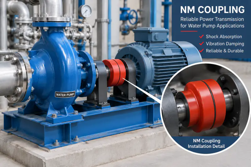
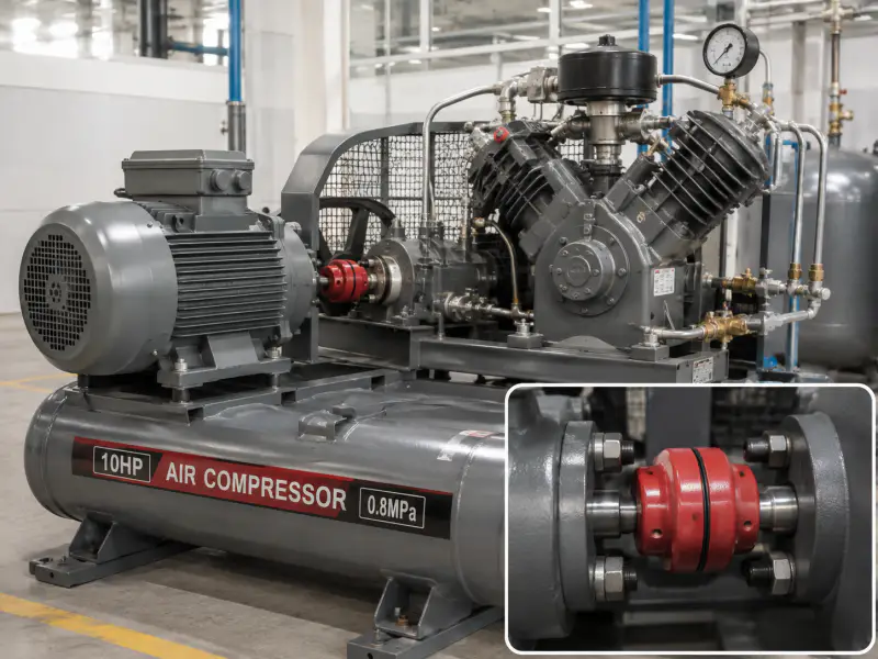
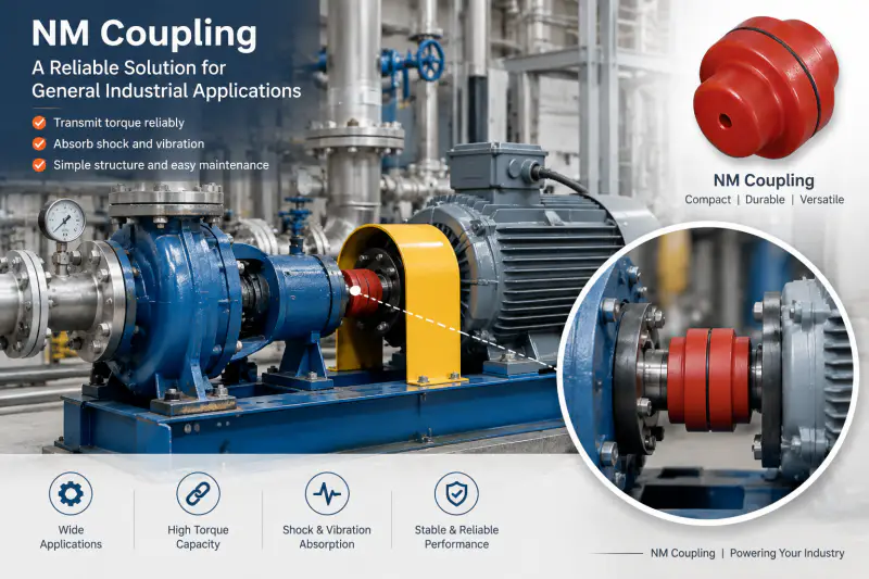
An NM 82 RFQ is best framed around the actual equipment duty. It can be reviewed for motor-driven pumps, blowers, compressors, automation equipment and other industrial machinery if the required shaft sizes and torque are compatible. Where the equipment cycles frequently, include starts per hour or the operating sequence so the review is not based solely on steady running conditions.
Interface Customization
Common project questions at this size involve finished bore combinations, key dimensions, fit tolerances and marking. If the existing coupling has an unusual shaft extension, spacer requirement or guard constraint, include a dimensioned photo or sketch. Those interfaces should be confirmed before cosmetic surface requirements are finalized.
Sample Planning
For samples, identify whether the goal is dimensional replacement, performance trial or approval of a custom bore. Batch quotations should include the expected model mix and annual or order quantity where known. This allows machining and inspection planning to be quoted on the correct basis.
Frequently Asked Questions
Why check torque and bore independently on NM 82?
The listed 10-32 mm bore range answers only the shaft-size question. The drive must also be checked against 5.0 Kg*m normal torque, transient load and operating speed.
What helps with a sample approval?
Explain whether the sample is for dimensional matching, fit testing or machine trial. That tells the supplier which dimensions and inspection records deserve emphasis.
Should alignment error be treated as free capacity?
No. The equipment should be aligned correctly during installation. Do not plan to use the flexible element as a substitute for correcting machine geometry.
What environmental data is useful?
State temperature range, lubricant or chemical contact, dust/washdown exposure and unusual cycling. The supplied sheet does not identify the center-element material grade.
Request NM 82 Review
Please include both shaft dimensions, motor power and speed or torque, quantity and application.